
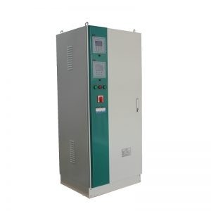
Transformer Rectifier
Transformer rectifier units (TRUs) are used to prevent submerged (Soil or water) metallic structures from corrosion. All submerged Pipelines (Oil, water etc.) and concrete structure of bridges/buildings / sea ports etc can be protected from corrosion by doing Cathodic Protection
TRUs impress DC Currents into the Carbon-steel/steel structure to be protected in opposite direction to the galvanic corrosion currents & protects the structure from corrosion.
To obtain the optimum level of protection under varying conditions, it is necessary to vary the impressed current continuously so as to maintain a constant level of protective potential at the structure. This continuous monitoring and control can be achieved by providing an automatic control for the cathodic protection system.

CUSTOMISATION
All external surfaces of oil tank are protected against corrosion for exterior, exposed, polluted atmosphere. The system comprises: Shot Blast to SA 2.5 Zinc flame spray - 100mm min d.f.t. Epoxy undercoat - 190mm d.f.t. Polyurethane topcoat- 250mm min d.f.t. (colour– BS 381C Shade 631 – light grey)
PROTECTION
The equipment is provided with the following devices for protection against over voltage and over current conditions. Primary 3 Pole MCB Semiconductor fuse in AC line to Diode Assembly Transient over voltage surge suppression on AC and DC sides of rectifier Voltmeter Fuses DC output fuse Control circuit fuse Electronic Voltage Limit Electronic Current Limit
CABLE ENTRY
The unit is fitted with a gland plate located at the bottom of the enclosure. Cable access should come from the bottom of the unit.
DC RIPPLE
Less than 5% from 5% to 100% of DC output.
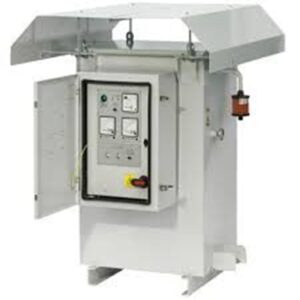
METERS
The unit is fitted with a DIN 72 DC Voltmeter, DC Ammeter and a Digital Ref. cell mV meter.
ACCESSORIES
The equipment is supplied complete with the following: Oil sight glass / oil temperature gauge Oil drain valve with protective kick plate and filler plug Silica – gel breather Rolled steel channel base for plinth mounting. Drilled to accept anchor bolts Lifting lugs and external earthing terminal Rating plate Operation and maintenance manual with circuit and outline drawings Test and inspection reports complete with a certificate of conformity Anticondensation heaters Sunshade Reference electrode meter Automatic potential control
TESTS
Insulation resistance test No load tests Load tests conducted DC output voltage and current. Full load input watts and current Efficiency Function tests
OPTIONAL EXTRAS
The following items can be supplied as optional extras: Current Interrupter Remote monitoring by 4-20 mA converters for connection to SCADA systems or SMS
| Environment Temperature | -30℃~+55℃ |
| Size | 1380×520×480mm |
| Weight | 260kg |
| Equipment Data | |
| Supply Voltage | 400 VAC +/- 10 % 3 PHASE |
| Frequency | 50 Hz +/- 5 % |
| DC Output Voltage | 50 VDC |
| DC Output Current | 50 A |
| Efficiency (Min) | 0.8 |
| Power Factor | 0.8 |
| Insulation Voltage (Ui) AC Side | > 3000 VAC for 1 minute |
| Operating Mode | Constant voltage |
| Constant current | |
| Constant potential | |
| DC Control Type | Thyristors (SCR) |
| Insulation Voltage (U) DC Side with Protective Devices | 1000 VDC for 1 minute |
| Insulation Voltage (U) DC Side Without Protective Devices | 1000 VDC for 1 minute |
| Max. DC Ripple | 5% (peak to peak) |
| Cooling Type | Oil |
| Oil Type | Borak 22 or equivalent(25#) |
| Unit Arrangement And Enclosure Type | |
| Location | Outdoor |
| Inside enclosure | |
| Installation | Plinth |
| Cable Inlet | Cable Gland |
| Enclosure Type | Metallic |
| Enclosure Thickness | 3mm |
| Enclosure Material | Metal Galvanized steel |
| Protection Degree (Min) | IP 54 |
| Paint Color | RAL7032 |
| Paint Cycle | Epoxy paint |
| Other Accessories | Anti-Condensation Heater Q Phases N°.: 1 Voltage:230V Power:50 W |
| Sunshade | DC current output |
| DC voltage output | |
| Protective potential |